Last time in Circuit Analysis Pt.1 we have got the methods to solve all the problems of DC resistive circuits, now we want to know how to solve All the circuits problems in some linear methods.
Apparently the differential equations are not linear, so if we want to make them linear, we have to change the equations into some other “forms”, into some other “domains”. We have to do some mathematical tricks.
- Here is an example:
- if we want to solve the following problem:
$$x^{2.35}=5$$ - We cannot do it directly, so we take the log of the both sides of the function:
$$2.35lg(x)=lg5$$
In the “log domain”, the function becomes linear.
$$lg(x)=\frac{lg5}{2.35}\approx\frac{0.6989}{2.35}\approx0.2974$$ - And then we check the logarithm table:
$$x=lg^{-1}0.2974\approx1.983$$ - That’s the answer.
Let’s do the same thing “ELECTRONICALLY”.
1. Phasor Method
First lets assume that our power sources are some AC sources.
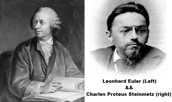
In 1748, L.Euler proved the function below:
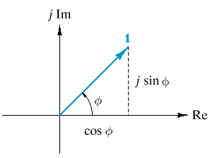
$$e^{i\phi}=cos\phi+isin\phi$$
Of course this function has a well-known version: Euler’s Equation:
$$e^{i\pi}+1=0$$
In 1893, C.Steinmetz use this function developed his AC steady state circuit theory, he use this function to turn all the sinusoidal quantities into complex numbers: phase vectors (phasor). In this way, the VCRs of R, L, C are all linear.
$$\dot{U_m}=R\dot{I_m}$$
$$\dot{U_m}=\frac{1}{j\omega C}\dot{I_m}$$
$$\dot{U_m}=j\omega L\dot{I_m}$$
Now the R, L, C become the same kind of linear quantity - impedance. We can use KVL or KCL or Thevenin’s theorem to solve the problems, just like what we did in the old days. Don’t forget to turn these phasors into sinusoidal quantities in the end, because these phasors actually don’t have any physical meanings.
2. Voltage Triangle and Power Triangle
Now you may have found that the voltages across R, L, C have different angles. That make the voltages in an AC circuit are shaped into a “voltage triangle” in the complex plane.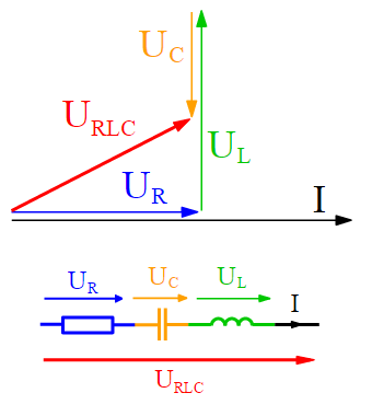
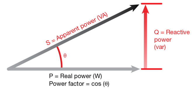
And think about the Power, the “U”s simply become “P”s, that’s still a triangle: the power triangle.
The real part of $U_{RLC}$ is consist of $U_{R}$, that explains that resistors are the
components in the circuits that consume energy. The imaginary part of $U_{RLC}$ is made of $U_{C}$ and $U_{L}$, that explains that capacitors and inductors simply “charge” the energy into other forms (electric field and magnetic field) and then they can get the energy back, they don’t really consume energy.
So we give $P$, $P_{real}$ and $P_{img}$ names: complex power ($\dot{S}$), active power or real power (P), and wattless power or reactive power (Q). The length of complex power is called apparent power (S).
3. Resonance
Another interesting fact you may have found here is that the angles of $U_{L}$ and $U_{C}$ are just the opposite: $90^\circ$ and $-90^\circ$. So what happened if they offset each other? Just like there are only resistors in the AC circuit. This is called resonance.
This will happen when: $|j\omega L|=|\frac{1}{j\omega C}|$ , so: $\omega_{0}=\frac{1}{\sqrt{LC}}$. This means that resonance just happens when the circuit reaches particular frequency.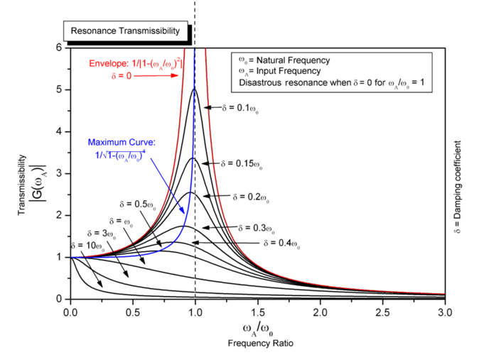
Here are some other definitions:
- Quality Factor:$$\begin{aligned} Q=\frac{\omega_{0} L}{R}=\frac{1}{\omega_{0} RC} \end{aligned}$$
- Bandwidth:$$\begin{aligned} BW=\omega_{high} - \omega_{low}= \frac{R}{L}=\frac{\omega_{0}}{Q} \end{aligned}$$
4. Maximum Power Transfer Theorem
We have already solved the same problem in DC circuits by using Jacobi’s Law. There are just something slightly different in AC circuits: the impedance has a imaginary part. So let’s just offset this part.
$$\begin{aligned}
Z_{L}=Z^{*}_{S}\\
P_{Lmax}=\frac{U^2_{S}}{4R_{S}}
\end{aligned}$$
HOWEVER, if you cannot change the angle of your load, then $Z_{L}=Z_{S}$ is good enough.
5. Circuits with Mutual Inductance
Inductors are interesting components. One inductor can deposit the energy into magnetic field and then another one can withdraw the energy: the transformer. Actually, we can use some calculation to get the equivalent forms of transformers or coupled inductors to turn them into some independent components in the circuits.
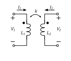
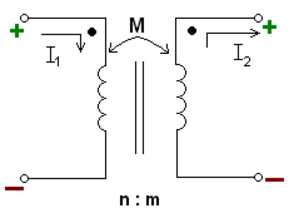
VCR of coupled inductors:
$$\begin{aligned}
u1=L_{1}\frac{di_1}{dt}+M\frac{di_2}{dt}\\
u2=L_{2}\frac{di_2}{dt}+M\frac{di_1}{dt}
\end{aligned}$$
And in phasor form:
$$\begin{aligned} \dot{U_1}=j\omega L_1 \dot{I_1}+j\omega M \dot{I_2}\\ \dot{U_2}=j\omega L_2 \dot{I_2}+j\omega M \dot{I_1} \end{aligned}$$The two dots in the circuit are dotted terminals, they show the direction of currents (actually the twining directions of the wires). If the dotted terminal on one side change, the functions above also change.
$$\begin{aligned}
u1=L_{1}\frac{di_1}{dt}-M\frac{di_2}{dt}\\
u2=L_{2}\frac{di_2}{dt}-M\frac{di_1}{dt}
\end{aligned}$$
Other definitions:
- Coupling coefficient:$$\begin{aligned}
M=k\sqrt{L_{1}L_{2}}
\end{aligned}$$
k is the coupling coefficient and 0 ≤ k ≤ 1.
- T-shaped inductors equivalent transform:
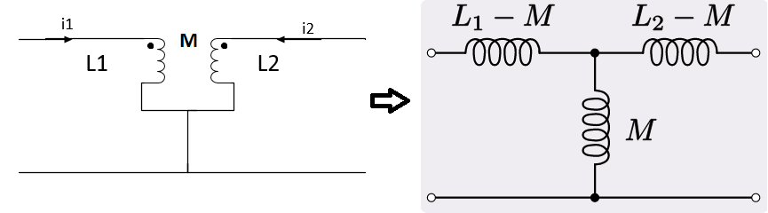
- Reflected impedance:
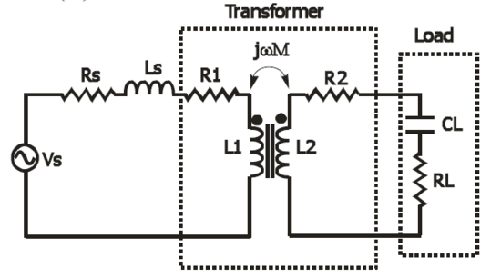
Input impedance:$$\begin{aligned} Z_{i}=\frac{\dot{U_{s}}}{\dot{I_1}}=Z_{primary coil}+\frac{\omega^2 M^2}{Z_{secondary coil}} \end{aligned}$$ $\frac{\omega^2 M^2}{Z_{secondary coil}}$ is called reflected impedance. - Ideal transformers:
Just the voltages across these two inductors change, so it can be solved normally.
Mmmm, that’s all about the phasor method I’ve learned so far.
However…
Phasor can only solve AC circuit problems. Is there a more generally applicable linear method to solve ALL the circuit problems??
References:
- Li,Hansun. Basis of Circuit Analysis, 4th ed. [M]. Beijing: Higher Education Press, 2007.
- Lin,Chunying. Electric Circuits and Magnetic Circuits, 2nd ed. [M]. Beijing: China Electric Power Press, 2014.
- Wikipedia [EB/OL]. https://en.wikipedia.org, 2016-01-28.