Circuit analysis is the process of finding the voltages across, and the currents through, of every component in the network, for voltages and currents are the basic values of components. Once you got the U (Voltage) and I (current) of a component, it’s easy for you to know how the component works. There are many different techniques for calculating these values. However, for the most part, the applied technique assumes that the components of the network are all linear. Not like something inside the electromagnetic field whose U-I relational expression is a function with space and time as variables, components in a linear circuit network is much more lumped and abstract.
The foundation of circuit analysis is basically built by 3 people, in the 19th century.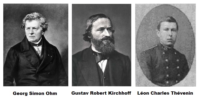
1. Ohm’s Law
$$U={R}\times{I}$$
Actually in 1781 Henry Cavendish discovered the above law first but he was unwilling to share it with people, so after Ohm published his result of his work on resistance in 1827, this law was named after him but not the real first discoverer.
In my opinion, the Ohm’s Law shows a character of common materials: They “resist” the current running through them. In other words, alomst everything can consume energy, and the ways they consume energy have to obey this rule.
And this law is exactly the foundation of everything in linear circuit analysis.
- By the way, we have to be aware of the reference directions in the circuits. If in your circuit, you assume that the voltage across a component is in the opposite direction with the current running through it, the Ohm’s law should be written as:
$$U=-{R}\times{I}$$
2. Kirchhoff’s circuit laws
- KCL: The algebraic sum of currents in a network of conductors meeting at a point is zero.
$$\sum_{k=1}^n I_k=0$$ - KVL: The algebraic sum of the products of the resistances of the conductors and the currents in them in a closed loop is equal to the total emf available in that loop.
$$\sum_{k=1}^n U_k=0$$
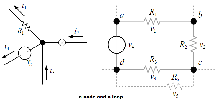
These laws are actually another ways to express the spirit of the conservation of matter and energy. Using these 2 laws we are capable of solving some more complex circuit problems but not just the basic series circuit or parallel circuit problems. On the basis of these 2 laws, we have the methods of nodal analysis and mesh analysis. Now we can solve every problem of a DC circuit with resistors and dependent source in it.
- BY THE WAY, sometimes we may find some odd parts in a circuit like these:
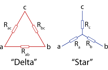
- In this case, we have to simplify the circuit by doing the Y-Δ transform.$$\begin{aligned} R_y=\frac{R'R''}{\sum{R_{\Delta}}} \end{aligned}$$ $$\begin{aligned} R_\Delta=\frac{R_1R_2+R_2R_3+R_3R_1}{R_{opposite}} \end{aligned}$$
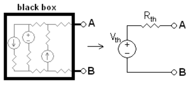
3. Thévenin’s theorem
As originally stated in terms of DC resistive circuits only, Thévenin’s theorem holds that:
- Any linear electrical network with voltage and current sources and only resistances can be replaced at terminals A-B by an equivalent voltage source in series connection with an equivalent resistance.
- This equivalent voltage $U_{oc}$ is the voltage obtained at terminals A-B of the network with terminals A-B open circuited.
- This equivalent resistance $R_{th}$ is the resistance obtained at terminals A-B of the network with all its independent current sources open circuited and all its independent voltage sources short circuited.
Now we can not only solve complex linear circuit analysis problems, but also transform the complex circuits into their simplified “Thevenin” equivalent forms.
- BY THE WAY, let’s think about how much power we can get from the circuits and how to get the maximum power.
- Around 1840, Moritz von Jacobi published the maximum power (transfer) theorem: the “Jacobi’s law”.
- to obtain maximum external power from a source with a finite internal resistance, the resistance of the load must equal the resistance of the source as viewed from its output terminals. So here we get:$$\begin{aligned} R_{L}=R_{th}\\ P_{max}=\frac{u^{2}_{oc}}{4R_{th}} \end{aligned}$$
- MEANWHILE, sometimes we may find some strange but useful components in our circuits, their U/I are not determined by their own I/U but the I/U of other components. They are dependent sources: VCVS, VCCS, CCVS, CCCS. They are very useful if we want to control the U/I of our target components.
However…
Resistance is only one of the 3 basic characters of materials. The other 2 characters are capacitance (C) and inductance (L). If we take them into consideration, the U-I relational expressions we get are:
$$i(t)=C\frac{du}{dt}$$
and
$$u(t)=L\frac{di}{dt}$$
- It’s worth noting that: because of the conservation of matter and energy, the voltage across a capacitor $u_C(t)$ and the current inside a inductor $i_L(t)$ cannot change instantly but can only be changed gradually and continuously. They are the state variables of the circuit.
Apparently, these equations are no longer linear. If there is only 1 capacitor or inductor in a DC circuit ( RC circuit or LC circuit ), we can use differential equations to solve them.
For example:
- $y(t)$ means a voltage or current in a circuit.
- $y(0_+)$ means the initial value.
- $y(\infty)$ means the stable value.
- $\tau$ is the time constant of the circuit. ( $\tau=RC$ or $\tau=\frac{L}{R}$ )
The point is: we must figure out the 3 elements: $y(0_+)$, $y(\infty)$ and $\tau$, so that we can solve the circuit.
$$y(t)=y(\infty)+[y(0_+)-y(\infty)]e^{-\frac{t}{\tau}}$$
MISSION ACCOMPLISHED.
However…
If there are many capacitors and inductors in a circuit, or the source of the circuit is not DC, it will be very exhausting to deal with it by solving differential equations. How can we solve it in some linear methods??
References:
- Li,Hansun. Basis of Circuit Analysis, 4th ed. [M]. Beijing: Higher Education Press, 2007.
- Wikipedia [EB/OL]. https://en.wikipedia.org, 2016-01-24.